01Home
02JPIoT
03Services
04About
05Contact

JPiOT / Hydroponic System

A connected viewof your growing environment.

Monitor the air and nutrient solution, manage dosing, and coordinate supported pumps, lighting and ventilation from one hydroponic control system.

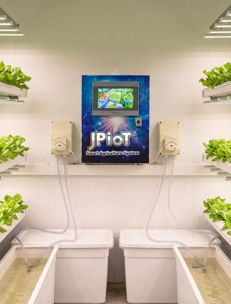
An indoor growing room: tiers of lettuce under LED bars along both walls, with a JPiOT controller on the end wall above two nutrient tanks and their dosing pumps
Project photographAn indoor growing room at an installation: the controller between two nutrient tanks, with a dosing pump on each side.

Overview

One system, three jobs.

In an indoor farm, every condition the crop meets is one somebody set. This system reads those conditions, can act on them within the limits it is configured with, and shows you what is happening.

  1. 01

    Monitor

    Light, air temperature, humidity and CO₂ in the growing area; pH, EC and temperature in the nutrient solution.

  2. 02

    Automate

    Within the configured logic, it can run the dosing pumps, the circulation pump, the grow lights and the fan connected to it.

  3. 03

    Review

    A 7-inch touchscreen on the controller, plus remote monitoring and Telegram where configured.

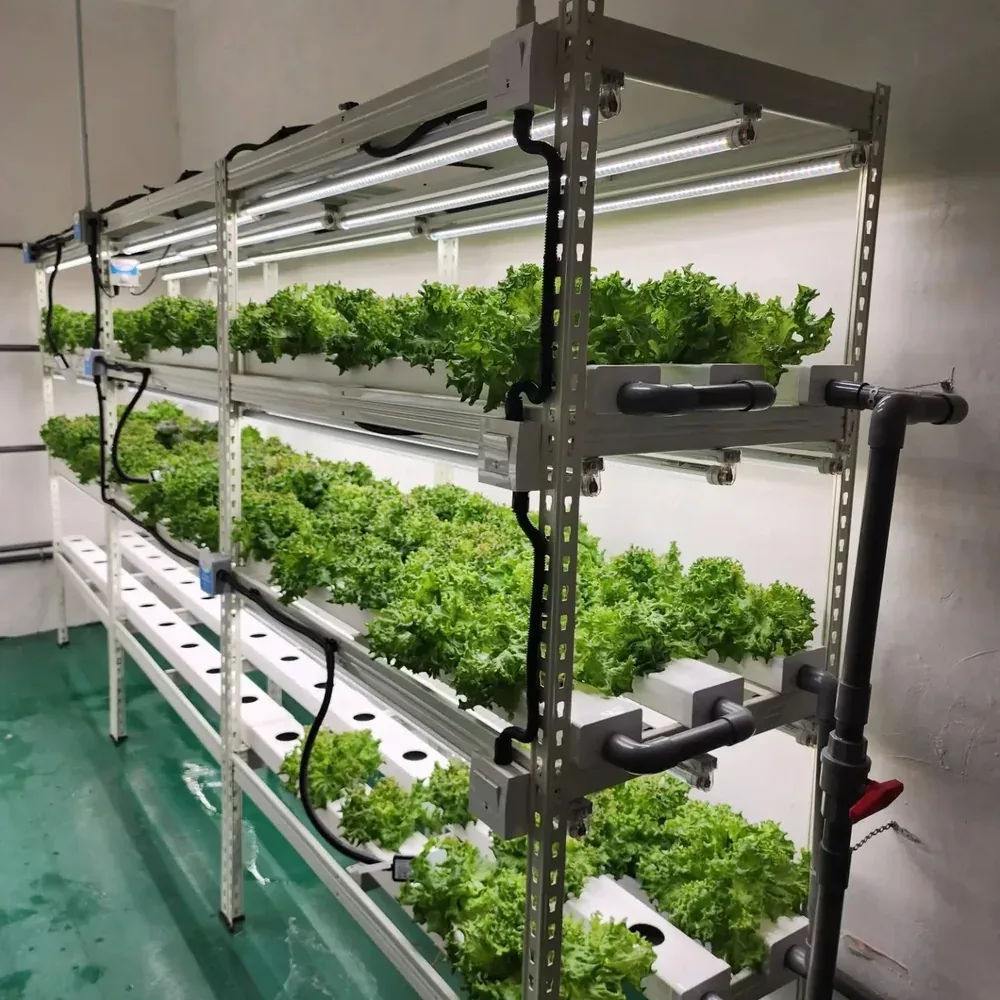
Three tiers of lettuce growing in white channels under LED bars, with black feed pipes running along the rack
A growing rack at an indoor installation.

What it can operate and what is supplied are two different lists; the second one is your quotation.

Monitoring

Understand the room. Understand the feed.

Two groups of readings, taken in two different places in the same growing system.

A drawing of the growing area: grow lights above the growing channels, a fan, and the environment sensor unit hanging in the room.Grow lightsGrowing channels

01Environment: the air around the crop

Light intensitylux
How bright the growing area is, read in lux in the product materials. Lux describes light as the human eye sees it; it is not PPFD, the light measure used for photosynthesis, and converting between them needs information about the light source.
Air temperature°C
The air around the crop, so you can see how warm the room runs through the day.
Humidity%
How much moisture the air holds, read as relative humidity.
Carbon dioxideppm
The CO₂ level in the air of the growing area. The reading shows the level; it does not mean CO₂ injection is installed.
VPDderived
Vapour pressure deficit, worked out from air temperature and humidity rather than measured by a sensor of its own. It summarises how “drying” the air feels to the plant.
A drawing of the nutrient reservoir with pH, EC and temperature probes in it, the circulation pump feeding the growing channels, and the return flow back to the reservoir.Nutrient reservoirpHEC°CTo thechannelsReturnflow

02Nutrient solution: the feed that reaches the roots

pHacidity
How acidic or alkaline the solution is, which affects how available the nutrients are to the roots.
ECµS/cm
Electrical conductivity: it rises with the dissolved salts in the solution, so it indicates overall strength. It does not measure each nutrient separately.
Solution temperature°C
How warm the solution in the reservoir is. Monitoring it does not imply a chiller or heater is part of the system.

Any example readings on this page are examples only. The right values for your farm depend on the crop, its stage and your growing method.

Measuring is not controlling. A reading tells you the condition. What the system does about it depends on the equipment connected and the logic configured for your installation.

Automation

From a reading to a controlled response.

Choose a step. The schematic highlights the parts involved and says what happens there.

Illustrative system flow · recirculating arrangement

1 Sensors readEnvironment sensors in the growing area read light, air temperature, humidity and CO₂, while probes in the reservoir read the solution’s pH, EC and temperature.

2 Controller receivesThose readings arrive at the JPiOT controller, which shows them on the touchscreen and, where configured, passes them on for remote monitoring.

3 Logic checksThe controller compares the readings with the targets and rules configured for your crop and installation. There is no universal setting: those values are set when the system is set up.

4 Equipment respondsWithin that logic, the controller can run the fertiliser A and B dosing pumps, pH-up or pH-down dosing as the reading calls for, the circulation pump, the grow lights and the fan — as far as the equipment connected at your installation allows.

5 Monitored againThe solution returns to the reservoir and the sensors read the new conditions, so the same loop runs again.
Hydroponic system flow: illustrative schematicAn illustrative recirculating arrangement. Environment sensors read light, air temperature, humidity and carbon dioxide in the growing area, and probes in the nutrient reservoir read pH, EC and solution temperature. The readings go to the JPiOT controller, which, following its configured logic, can operate the fertiliser A and B dosing pumps, the pH-up and pH-down dosing pumps, the circulation pump, the grow lights and the ventilation fan. Solution is pumped from the reservoir through the growing channels and returns to the reservoir, and the sensors read the new conditions.JPiOT controllerECpHLED grow lightsGrowing channelsFan /ventilationLightAir tempHumidityCO₂VPD (derived)Nutrient reservoirpHEC°CABpH+pH−Dosing channelspH up or down,only as neededCirculation pumpReturn to the reservoir Hydroponic system flow: illustrative schematicAn illustrative recirculating arrangement. Environment sensors read light, air temperature, humidity and carbon dioxide in the growing area, and probes in the nutrient reservoir read pH, EC and solution temperature. The readings go to the JPiOT controller, which, following its configured logic, can operate the fertiliser A and B dosing pumps, the pH-up and pH-down dosing pumps, the circulation pump, the grow lights and the ventilation fan. Solution is pumped from the reservoir through the growing channels and returns to the reservoir, and the sensors read the new conditions.LightAir tempHumidityCO₂VPD (derived)LED grow lightsFanGrowing channelsJPiOT controllerECpHABpH+pH−Nutrient reservoirpHEC°CCirculation pumpReturn tothe reservoir
  • Nutrient solution
  • Fertiliser A
  • Fertiliser B
  • pH adjustment (up / down)
  • Reading to the controller
  • Command to equipment

Illustrative system flow. Not an installation drawing, and not an equipment-control interface.

Equipment

What the controller can operate.

Choose a part of the drawing. What it can operate and what is supplied are two different lists.

Equipment layout: schematic drawingA drawing of the JPiOT controller with its 7-inch touchscreen, the four dosing pumps around it for fertiliser A, fertiliser B, pH up and pH down, and the circulation pump, LED grow lighting and ventilation fan it can operate.LED grow lightingJPiOTHydroponic SystempH uppH downFertiliser AFertiliser BCirculation pumpFan / ventilation

Schematic drawing of the equipment layout, not a product photograph.

Choose a part to read about it. Seven parts are marked on the drawing.

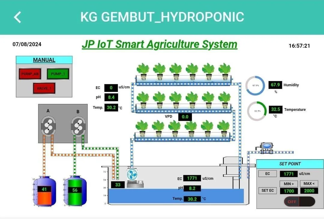
The JPiOT system screen from the project document, showing a diagram of the reservoir, dosing units, growing channels and the readings beside them
The system screen, as captured in the supplied project document on 7 August 2024. The values on it are that site’s readings that day, not recommended settings.

Operated versus supplied. Pumps, lights and fans already on your farm may be able to connect. The equipment included in your system is the list in your quotation.

Electrical specifications. Relay counts, electrical ratings, supported loads and enclosure ratings are not published here. Ask for the specification of the configuration you are quoted.

In the field

From installation to daily growing.

Photographs from the supplied project document, and the figures reported in it.

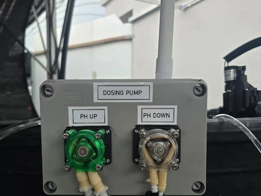
  1. A dosing pump box labelled pH UP and pH DOWN mounted above a tank at an installation
    01 · InstallationDosing installed at the site, with labelled pH-up and pH-down pumps above the tank.
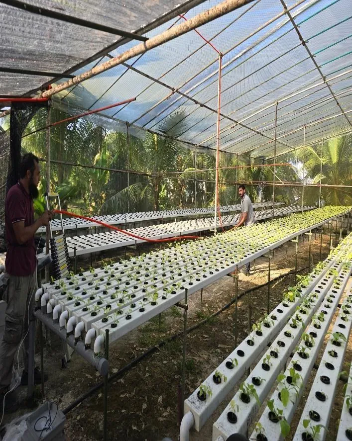
  2. Rows of hydroponic growing channels inside a daylit protected structure
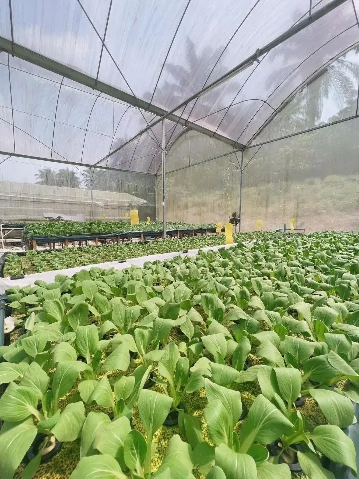
    02 · Growing setupGrowing channels under a daylit protected structure, not a fully enclosed LED room.
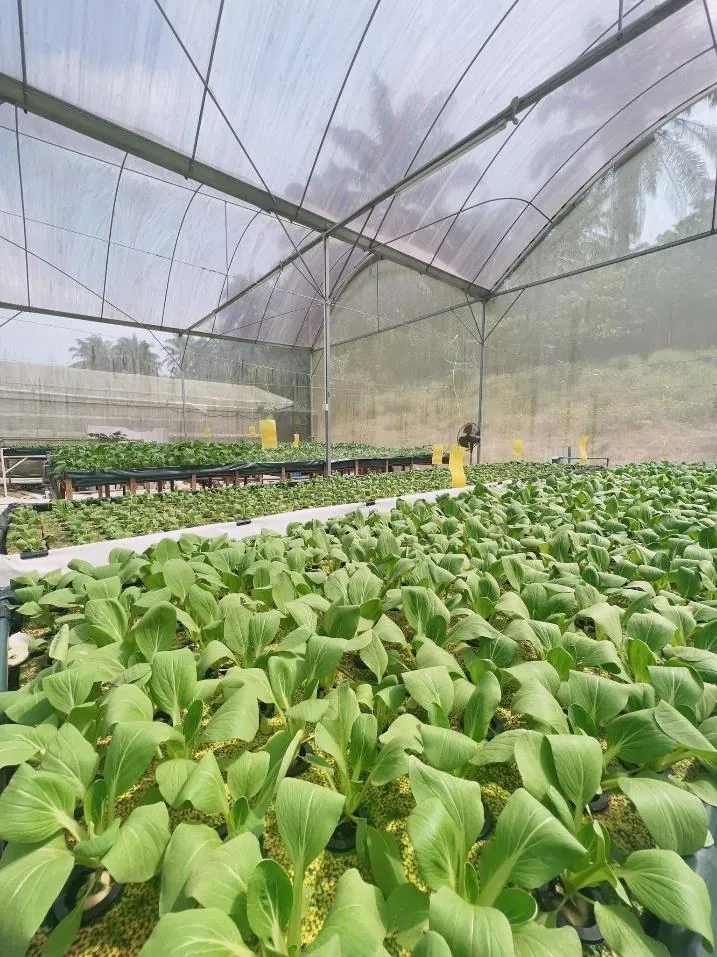
  3. Pak choi filling the growing channels, photographed close up
    03 · The cropPak choi in the channels, photographed in the same project document.

Reported results from the supplied project document

Before and after figures as reported in the project document
MeasureBeforeAfter
Harvest cycle Before31 days After26 days
Yield per table Before58 kg After78 kg
Total across seven tables Before406 kg After546 kg
Fertiliser use BeforeNo baseline figure reported After15% more used

Calculated from the figures above: a 5-day shorter cycle, 20 kg more per table, and 140 kg more across seven tables.

The document also describes the plants in the after condition as fresher, more uniform and larger, with less yellowing, and states that 15% more fertiliser was used in that condition.

These are results reported in the project document supplied to us, for one growing operation. They are not an independently validated controlled trial and not a guarantee: outcomes depend on the crop, the growing conditions, how the system is operated and how it is installed.

What it watches

A living view of the farm.

Follow the latest readings from our connected farm sensors.

Values appear as each sensor reports them, except weight: shown in kilograms, with a reading below zero as 0 kg.

Weight scale

Straight from the scale.

The newest reading from the weighing scale on the farm above, on its own. A scale weighs everything on its platform together: in a growing setup, the container, medium, crop and the water the medium holds, so watering raises the reading and drying brings it down.

Farm

JPiOT · Telegram monitoring

Your farm.
Your data.
One conversation.

Check the conditions that matter, right from Telegram. Choose a system, open a sensor, and see its reading, status and next step.

Try the interactive demo. No Telegram account needed.

  1. 01Choose a system
  2. 02Select a sensor
  3. 03Read the response
JP Demo(MAHA 2026)Farm Pulse · bot preview
Live farm data
Interactive preview · No messages are sent to Telegram.
7 systems. 31 sensor readings. One place to explore them.Readings from our demo farm. Bot layout from supplied screenshots.

This shared JPiOT demo includes features across different monitoring configurations. Sensors and integrations for your hydroponic installation are confirmed in your quotation.

From installations

Real setups, photographed on site.

Four pictures from sites that have been installed. Each caption says only what is in its frame.

  • Three tiers of lettuce in white channels under LED bars, with feed pipes along the rack
    Indoor roomLettuce in channels under LED bars, with feed pipes running along the rack.
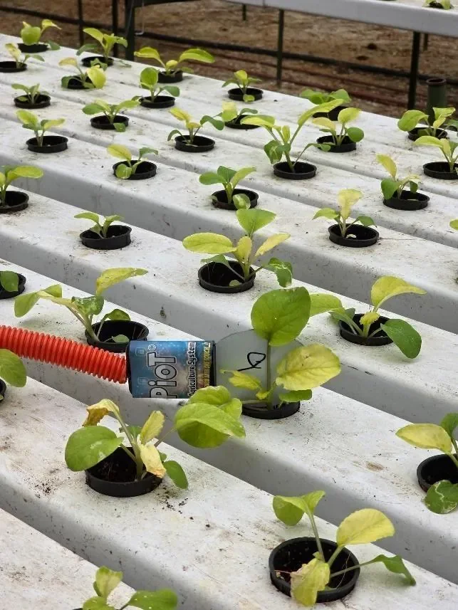
  • Young pak choi seedlings in white NFT channels, with a JPiOT sensor unit resting on the channel beside an orange conduit
    Sensor at the channelSeedlings in NFT channels, with a labelled JPiOT sensor unit on the channel.
  • Rows of pak choi in channels filling a net house, with a fan on the far wall and daylight through the roof
    Under a net housePak choi filling the channels under a daylit net-house roof.
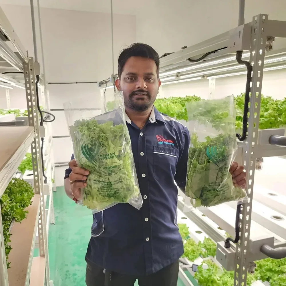
  • A member of the JP Global team holding two bagged heads of lettuce in an indoor growing room
    Harvest dayLettuce bagged inside the same kind of indoor growing room.

Photographs from sites, supplied by JP Global. They show growing setups, not measured outcomes; the reported figures are in the results section above.

Enquire

Let’s plan the system around your growing setup.

Tell us about your farm. Your answers go into a WhatsApp message you can check before sending.

Prefer to call?+60 10-211 0447

Opens WhatsApp with your answers filled in. Nothing is sent until you press send in WhatsApp.

Enquire